

Thermal Simulation of Automotive Lamps Using Ansys ICEPAK
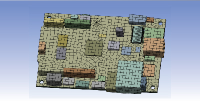
Lighting Systems play an important role in human factors of safe driving. It is an essential part of any vehicle and has undergone significant changes and advances in lighting technology over the years. Thermal aspects play a crucial role when it comes to the designing of automotive lights. Automotive lighting systems mainly consist of outer lens, inner lens, housing, reflectors, bulb, bezel, Led, PCB and light guide, etc.. Automotive headlamp Out of the parts mentioned above, bulb and led are the two primary sources of lighting that generate a lot of heat energy. Hence it is essential to design the automobile lamps such that even at an extreme ambient temperature, the temperature on each part is maintained well below the critical limit. The critical limit is usually the heat deflection temperature & the maximum temperature on the parts of the lighting system should be well below their respective material HDT values. The role of CFD simulation in Automotive lamp designing? Generates polyhedral meshes, polyhedral prisms can easily uphold mesh quality for refined boundary layer regions. Offers wrapping advantage to mesh large assemblies. Parallel mode execution without using any HPC licenses, consistent speed scale-up. Can run with both Solver and Pre-post license. Coming to the main question – “What is the role of Computational Fluid Dynamics and software tools such as Ansys in designing the automotive lighting system”? CFD simulations can play a crucial role in optimizing various design parameters such as lamp size, the distance between bulb and lens, number of vents, vent location, and selection of materials according to the design requirements. The thermal simulation of automotive lamps comes under conjugate heat transfer type of analysis in which all the modes of heat transfer are essential to model. Radiation is the key source of heat transfer in lamps. Radiation affects the heat wattage from the filament or led source chip and increases the following – temperature of the bulb, reflector, housing, lens, etc. Hence, proper selection of the radiation model is important to get accurate results. Since many parts are interlinked, thermal conduction plays a crucial role in heat distribution especially when automotive lighting systems contain Led chips and PCB. As all three modes of heat transfer are involved in this simulation, various parameters are needed to benchmark to get the correct results. There are mostly three kinds of simulation done for Automotive lamps as follows: Simulation of Headlamps: The bulb of the headlamp consists of two filaments called High beam and Low beam filament. The Low beam filament is situated closer towards the lens and the High beam filament is placed closer towards the bulb holder. Generally, analysis of the former is more preferred than high beam one because when the Low beam filament is switched ON, the lamp parts get more heated. However, some companies also tend to perform analysis by turning ON both high beam and low beam filaments to predict the maximum temperature in the worst-case scenario. Simulation of Taillamp: Tail lamps are generally smaller in size as compared to headlamps, so to avoid high temperatures, they should be carefully designed. Tail lamps consist of tail function filament and stop function filament. Tail lamp simulation is done by turning ON both the tail function and stop function filament. Simulation of Front turning lamp: Headlamp consists of a signal turning bulb. Sometimes companies prefer to simulate the headlamps along with the front turning lamp. Often, two turning signal bulbs will be at the sides of headlamps. These two signal lamps may contain separate reflector parts and lens parts. The wattage of these bulbs is generally small, but as these signal bulbs are cramped to a smaller area, it may end up heating the lens and reflector way above HDT values. That is why engineers very often perform simulations for these lamps as well. Table 1: Lamp Main parts and material description: Parts Most Preferred Material Heat deflection temperature range Outer Lens Plastics 100°C -140°C Housing PMMA 90°C-120°C Reflector PMMA/Plastics 90°C-120°C Bulb Glass N. A Bezel Plastics/PET+PBT 90°C -140°C Inner lens Plastics 100°C -140°C The main aim of the simulation is to predict the temperature distribution in various lamp parts and to find out if the maximum temperature is greater or lesser than the Heat deflection temperature. This can help the design team to select the best material according to the design requirement. The simulation can also help the design team to decide the proper locations of air vents by predicting the air-flow path and location of maximum temperature. Advantages of using Ansys Icepak in Automotive light thermal simulation: Ansys Icepak is the most popular tool in the market when it comes to electronics cooling simulation. It uses Fluent as a solver which is one of the most reliable and popular solvers when it comes to CFD. The top advantage of using Ansys Icepak is that it saves us from the tedious task of generating fluid domain. It can automatically generate fluid domain using a cabinet or enclosure approach and creates hexahedral mesh easily. Using Icepak we can save a lot of time which we spend in generating fluid domain and creating a high-quality mesh. Moreover, Ansys Icepak has various radiation models, such as S2S, DO, Ray, tracing models which can be used both for participating and non-participating mediums accordingly. To show the capability of Ansys Icepak in simulating automotive lighting systems, a quite simple model of an Automotive headlamp is developed using Spaceclaim. Please note that this cad design is in no way sponsored by or affiliated with any organization. Lamp without lens Vents Bulb Outer lens Lamp Parts Icepak Simplification: The Spaceclaim objects will be converted into icepack objects using the Icepak simplification feature available in Spaceclaim. Conversion to icepack objects is necessary and every geometry part must be converted to icepack objects through icepack simplification in space claim or design modeler. Conversion of Spaceclaim parts to Icepak objects Mesh created in Icepak Effort less meshing using Ansys Icepak: Ansys Icepaks’ HD Mesher generates
Fast-Tracking 5G & Advanced Driver Assistance Systems (ADAS)
Roadmap from 1G to 5G-ADAS From the past few decades, the world has witnessed many versions of a cellular network, 1G version was a basic voice communication system that supported only Analog modulation. The flavour of data connectivity was present in the second version that used in digital technology. 3G version flavoured highly improved data connectivity using technologies such as Wideband Code Division Multiple Access (WCDMA) and High-Speed Packet Access (HSPA). Currently, 3G is the largely sold version of cellular networks around the globe although the next 4G network version is closing the gap quickly. The third and fourth generations (3G and 4G) of mobile communication technologies are widely deployed, providing voice and mobile broadband as their main services. Presently the world is enjoying the pleasure of 4G that uses orthogonal frequency division multiplexing (OFDM) technology to provide bandwidth of 20 MHz with Multiple Input and Multiple Output (MIMO) antenna transmission Technology. The world is progressing rapidly towards next-generation cellular communication and is on the verge of entering into the 5G era, with completely new infrastructure and technology. A challenge of today’s 5G research is in the waveform frequencies that are being used around the world as signals will suffer from more noise at these frequencies. And these noise levels can be minimized to some extent by performing proper filtering at waveform level but can be reduced majorly by applying proper signal processing technique at the transmit antenna side and receive antenna side. FBMC is an upgraded version of OFDM, which offers benefits such spectral efficiency and resistance to multipath with zero inter-carrier interference and is expected to come with 5G. There is a rapid increase in demand for high definition multimedia streaming around the world. The currently utilized microwave frequencies won’t be sufficient to meet this demand due to a shortage of bandwidth. We need up-gradation to mm Wave frequency bands that provide a larger bandwidth to meet this demand. Several GHz of the spectrum at mmWave frequencies provide an abundance of bandwidth to support GBPS data rates. This abundance in bandwidth helps to incorporate large array that provides high directivity to combat path loss and reduced interference. We can successfully transmit a huge amount of data known as BIG DATA by utilizing these spectrums. The signal at these higher frequency band suffers higher path loss and rain attenuation due to which it is not suitable for outdoor communication. The wavelength of mmWave signal is very small due to which it becomes practicable to embed the multiple numbers of antennas that will direct the signal into highly concentrated beams with sufficient gain to master propagation loss. This process of sharpening of beams is called beam formation, where signals will be added constructively at some point in space. Upcoming 5G systems are predicted to introduce these profound technologies. Why 5G? The urge for data usage is increasing day by day globally and the existing LTE network needs to be improved with LTE-Advanced that provides bandwidth till 100MHz. Even though it is continuously updated through new releases, and with LTE Advanced Pro Release being the latest one, the development of the fifth generation has been initiated. After a few more year’s LTE-Advanced technologies won’t be sufficient to satisfy the increasing data urge around the world and there will be a need for the new version of a cellular network that can satisfy the data requirements in coming years. 5G network is visualized to simplify the burden on current cellular infrastructure by offering significantly higher data rates through increased channel bandwidth. 5G communication system is expected to exploit the spectrum band at millimetre-wave (mm Wave) frequencies. But the mobile communication at these mm Wave spectrum band is far more complex than the current frequencies that are being used around the world as signal suffers higher propagation loss. Antennas for next-generation 5G will make use of shorter element size at high frequencies to incorporate beam formation capabilities. This helps to increase the capacity of the cellular network by improving the signal to noise ratio (SNR) and maintain an optimal BER (Bit Error Rate) at mm Wave frequencies. 5G mobile network offers a vision of “everything everywhere and always connected” which will make use of microwave and Millimetre-wave frequencies ahead of 24 GHz. 5G mobile network is surmised of providing minimum data throughput of 1 Gigabit per second. However, due to the increasing demand for higher data rates and larger system capacity, in addition to the emergence of new Internet of Things, ADAS, and safety-oriented mobility use cases, the fifth-generation (5G) is currently being discussed and developed. Different Dimensions of 5G Three Dimensions of 5G are: Massive Machine-Machine Communication (mIOT) Ultra-reliability-ADAS systems and Enhanced Mobile Broadband (eMBB) A key scenario for 5G, IoT, and ADAS System has connected mobility as shown in the above image, which utilizes vehicular communication for such things as infotainment, safety, and efficiency. While these requirements are already in the scope of 5G standardization, the ability to meet the requirements in practice is more important than ever because of the criticality of the safety-oriented connected mobility use cases. These cases rely on vehicular communication for such capabilities as platooning, cooperative awareness, and self-driving cars. CADFEM UNIQUE 5G ADAS SYSTEM PROTOTYPING Simulation enables innovative ideas, that can push products beyond their traditional limits, to be tested and realized without the burden of prototype costs and time. When engineering simulation software made its debut nearly 50 years ago, early adopters quickly distinguished themselves from those companies who were slower to recognize and embrace its potential. Tomorrow, it will be part of the toolbox for every engineer. As we push for ever-smarter and more efficient product designs like 5G, we can no longer afford to only look at a single aspect of performance or alone part in isolation. In the past, engineering simulation teams were likely to isolate just one critical physics. Today, thanks to improvements in simulation software, hardware, and processing speeds, it has become much easier for engineers to study
Integrated Functional Safety and Safety of the Intended Functionality Analysis using Ansys Medini Analyze

Functional Safety (FuSa) standards such as ISO 26262 have proved their immense importance to make the electronic components more reliable in today’s cars by delivering consistent performance and reducing critical system failures. However, with the rise of ADAS features, the autonomous driving capabilities in vehicles come with an even higher engineering challenge regarding safety and reliability. Sensors, and other components that are working as a designed part, are falling short of capabilities when running in real-time scenarios resulting in dangerous conditions. To address these types of challenges, a new standard safety of the Intended Functionality (SOTIF), ISO 21448 safety standard, will be soon introduced to identify shortfalls in the performance that can occur even when the system is in failure-free condition. It raises the expectation of every component works as designed, and the design is adequate to work to fulfill its goal with the required performance. On the other side, the new SOTIF standard requires a full range of safety analysis & engineering simulation solutions to enable autonomous vehicle development teams to build flawless performance into their designs right from the early stages of product development. The development team can validate the performance before the vehicle launch in the market. 1.1. What is ISO 21448: Road Vehicles – SOTIF? SOTIF is abbreviated Safety of The Intended Functionality and, in short for ISO/ PAS 21448, applies to functionalities that need a proper awareness of the situation to be safe. This standard concerns how to ensure the safety of the functionality even in the absence of a fault/failure. This is quite in contrast with the traditional Functional Safety (FuSa), which is majorly concerned with the risk associated with system failure. 1.2. How is ISO 21448 related to ISO 26262? ISO 26262 covers the functional safety of the system in the event of failures and has no coverage of safety hazards that result in the absence of system failures. That is the reason ISO 21448 is mandatory in analyzing the situations where ensuring safety without system failure is so complex and complicated. 1.3. Why is SOTIF (Safety of the Intended Functionality) important? In today’s world, vehicle electronics provides features like comfort, communication, and navigation assistance, mission-critical functionality such as steering and braking & more. The global automotive standard helps engineering teams to uncover and address FuSa hazards such as software bugs and hardware failures. Safety stakes have grown even higher, and if a crucial component, let’s say the sensor is not fulfilling its needed functionality or it fails to deliver the performance needed to handle a situation – for example, failing to recognize a pedestrian in the road ahead; the application of ISO 21448 helps us to ensure that the perception algorithm systems (a combination of sensors and software algorithms) will recognize pedestrians in all situations that are part of the Operational Design Domain (ODD). This enables the systems to trigger a safe response in consideration of performance under various ODDs. SOTIF ensures robust design against any disturbances and hazards due to flawed Human-Machine Interactions. Limited contrast resolution images in the presence of blinding sun A Model-Based Workflow Integrating FuSa and SOTIF: To successfully conduct autonomous vehicle development in compliance with both ISO 21448 and ISO 26262 there is a unique model that combines a linear process, V-shaped progression with feedback loops of evaluation and improvement to incorporate the learning and as well as comply with the standard. This model-integrated safety workbench offers all required analysis options for Functional Safety (FuSa), Safety of The Intended Functionality (SOTIF). The following is a step-by-step look at the workflow: Features of the Automated Driving (AD) functionality and the Operational Design Domain (ODD) are defined. From the above-portrayed functionalities, the requirements are derived or transferred from the Original Equipment Manufacturer (OEM) to the supplier. The initial architecture developed on a functional level, and this will begin the integrated FuSa and SOTIF process. Performing the hazard analysis and investigating the causes of potential hazards strengthens the feedback loop to identify the issues during the analysis stage and rectifies them straight from the initial level to the architecture level. Ultimately, this will enhance the requirements and architecture. Engineers execute the refinement and technical concretization of hardware, software, and sensor requirements and solutions, again handled in a model-based way, with a corresponding feedback loop. Performing model-based control software generation will help the engineer to generate safety compliant code, Automotive Safety Integrity Level (ASIL). Moreover, level D. Camera and radar sensor technologies and perception algorithms are validated, sent for evaluation, and improved in a cyclical process until an acceptable performance level for all foreseeable situations has reached. The integrated AD functionality is validated under realistic road conditions to prove that its behaviour is appropriate in every situation. This step includes closed-loop simulation, supported by optimized scenario variation and parameter assignment, as well as automatic identification of “edge cases.” All insights are imported back into the safety tool, closing the validation loop. Hardware, software, and the Electronic Control Unit (ECU) that support AD functionality undergo thorough integration testing on Hardware-In-Loop (HIL) benches. All the insights will get mentioned in a convincing safety case that includes a graphical view of requirements refinement and traceability of all artifacts in the model-based process to demonstrate safety. To maximize efficiency and financial returns, hardware, software, models, requirements, test cases, and other artifacts are available for re-use in future development efforts, typically with extended ODDs or extended functional capabilities. Medini Analyze as a Single Source for meeting SOTIF and FuSa Standards: Ansys Medini Analyze is a software tool, which has been recognized by a different industrial standard for analyzing varied aspects of functional safety, technical safety, and compliance with the standards. Performing SOTIF analysis individually, as a stand-alone activity, will empower the product operational safety analysis and make use of architecture models, vehicle-level malfunctioning behavior analysis, and hazardous event assessments. This can eliminate redundancies and ensure consistency among all the results. Ansys Medini Analyze has enhanced the model-integrated safety approach with new modeling elements for limitations,
Multiphysics solution for Electrical Machines at Design stage
Multiphysics solution for Electrical Machines at Design stage Now a day’s Electrical motor is the key component in the Autonomous World. We can find the Electrical motor in every application like Electric vehicles, Industries, Robotics, and renewable energy, etc,. Back in time, Electrical machine analysis was treated as a Single physics problem, But nowadays due to a lot of challenges, we treat the electrical machine as a Multiphysics problem. It has challenges in Electromagnetic, Mechanical, and Fluids as well. So, designing a highly efficient and cost-effective Electrical motor is challenging. However, the traditions to develop the motor has not yet completely changed. Most of the Motor R & D teams are depending on the standard methodology and Machine design Experts. This leads to consume a lot of time and thereby optimization of the Electrical machine will become much more complex. To overcome these challenges, Integrated Multiphysics simulation technology makes it possible to optimize Electrical machine design performance in a fraction of the time and cost required by traditional design methodology. It is “a true Multiphysics problem,” which requires precise attribute balancing across all the physics platforms. These interconnected attributes increase dependency across all departments, with the ultimate goal of “efficient and robust E Machine development.” Ansys Motor Solution at Design Phase: Ansys motor technology has a complete comprehensive solution from the initial design of the motor to high-end Multiphysics solutions. Apart from the high-end 3D simulations, Ansys can also address the Multiphysics platform in the Motor design stage. Ansys Motor-CAD is a Multiphysics simulation solution for Electrical rotating machines at the design stage. Which can offer the simulations to full torque-speed operating range. Ansys Motor-CAD quickly evaluates different machine topologies and produces the Optimized size, performance, and robust machine. To address the Multiphysics challenges, Ansys Motor-CAD has four modules. Electromagnetics (EMAG) Thermal (Therm) Mechanical (Mech) Virtual Laboratory (LAB) Nowadays the product development life cycle has reduced due to the competition. So, to meet the deadlines, motor designers should quickly validate their design data and need to make a quick design decision, and with certainty that they will not face problems down the line. The template-based solution and standard workflow will allow enough time for Motor-CAD users to explore multiple design variations and completely assess the complex Multiphysics challenges like the impact of advanced loss effect in the initial design stage. Electromagnetic Analysis (EMAG) Thermal Analysis (Therm) Virtual Laboratory (LAB) Mechanical Analysis (Mech) Electromagnetic Analysis (EMAG): Ansys Motor-CAD EMAG module is a combination of basic Finite element (FEA) analysis and analytical algorithms for quick analysis of the Electromagnetic behavior of the designs. It is 2D template-based & can accept customized .dxf* files as well. It will optimize the Motor designs easily with an extensive range of parametric-based platforms.Thermal Analysis (Therm): Ansys Motor-CAD Therm module has an industry-standard tool with 20+ years of experience in Motor thermal analysis. The thermal module has an extensive range of templates and it is working on 3D lumped circuit analysis to give a quick response within seconds. The complete geometry model will be treated as a thermal circuit with heat sources, resistances, and Capacitances. Motor-CAD therm will address both Steady-state and Transient thermal including the different types of cooling effects like forced convection, natural convection, etc.Virtual Laboratory (LAB): Ansys Motor-CAD LAB module is an equivalent extracted the saturated model from the EMAG module. The lab module enables the engineer to rapid and accurate prediction of Electrical motor design and performance for an extensive range of operating points. This Saturation model with different operating points helps the engineer to give a quick response for Efficiency maps and Torque speed curves within minutes. This model will carry out different duty cycle analyses within seconds.Mechanical Analysis (Mech): Ansys Motor-CAD Mech module works on Finite element analysis (FEA). This is a template-based geometry and will accept a .dxf* file as well. Mechanical module analyses the stress and displacement on the rotor front under high operating speeds.