
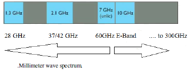
We need up-gradation to mm Wave frequency bands that provide a larger bandwidth to meet this demand. Several GHz of the spectrum at mmWave frequencies provide an abundance of bandwidth to support GBPS data rates. This abundance in bandwidth helps to incorporate large array that provides high directivity to combat path loss and reduced interference. We can successfully transmit a huge amount of data known as BIG DATA by utilizing these spectrums. The signal at these higher frequency band suffers higher path loss and rain attenuation due to which it is not suitable for outdoor communication. The wavelength of mmWave signal is very small due to which it becomes practicable to embed the multiple numbers of antennas that will direct the signal into highly concentrated beams with sufficient gain to master propagation loss. This process of sharpening of beams is called beam formation, where signals will be added constructively at some point in space. Upcoming 5G systems are predicted to introduce these profound technologies.
Three Dimensions of 5G are:

A key scenario for 5G, IoT, and ADAS System has connected mobility as shown in the above image, which utilizes vehicular communication for such things as infotainment, safety, and efficiency. While these requirements are already in the scope of 5G standardization, the ability to meet the requirements in practice is more important than ever because of the criticality of the safety-oriented connected mobility use cases. These cases rely on vehicular communication for such capabilities as platooning, cooperative awareness, and self-driving cars.
|
5G Simulation Prototype
|
5G-IC-Designer
|
5G-Package Designer
|
5G-Board Designer
|
5G-Antenna/System Designer
|
|---|---|---|---|---|
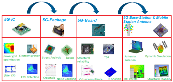
CADFEM can help & bring down your headache considerably whether you are involved with the design of Systems, Baseband, RF, or Antenna systems. CADFEM will explain how and why to do post-layout analysis, specifically how to use the Ansys SI wave field solver to extract layout parasitic into an EM-based model that you can add to the pre-layout circuit simulation. In this way, the spike voltages can be determined, and (using “What if…” design space exploration) reduced to an acceptable level before sending the layout for fabrication. Don’t smoke those precious power devices with expensive, time-consuming, non-deterministic board spins: use this “virtual prototype” method instead as shown in the below figure.

As 5G radio frequency (RF) and wireless communication components are integrated into compact packages to meet smaller footprint requirements while improving power efficiency, electromagnetic field simulation is the only way to make these trade-offs.
mm Wave 5G Smart Mobility Communication System requires more functionality in smaller multivariant packages. As the global power budget is reduced and the operating frequencies required to deliver rich features increase, engineers are confronting the issue of power supply noise. The chips, packages, and printed circuit board all contribute to power supply noise, so the complete system must be optimized to limit noise across the voltage and ground terminals of the transistors for error-free performance. SI Wave is a dedicated tool for electrical analysis of full PCB and complex electronic packages. SI Wave solves interrelated PI, SI, EMI challenges to deliver predictive analysis for your design. It provides solutions in both the Time & Frequency domains. HFSS 3D Signal Integrity Electronic Package Design access a streamlined 3D design flow that enables complete package system analysis with Seamless integration with EDA layout tools to create customized signal integrity, power integrity and EMI design flows.
Begin the simulation process by importing the electrical model of the integrated 5G Chip (PHY model and patterns), package and board, and various memory chip models provided by manufacturers into Siwave. Then solve the imported structures and perform multiple simulations to compute resonances, trace characteristics, discontinuity reflections, and inter-trace coupling. Engineers can extract S parameters, an IBIS interconnect model, and a full-wave SPICE model. These can be imported into Ansys Nexxim, SIwave’s circuit simulator, for time- and frequency-domain analysis. Nexxim can be used to generate time-domain eye diagrams and to check the data timing and voltage for overshoot and jitter of the 5G-High Speed Board. The port excitations can be set by drivers in IBIS format, pseudo-random bit sequence (PRBS) used can be used to reproduce real use cases. Eye diagrams can be used to indicate the allowable window for distinguishing bits from each other at the receiver end. The required height of the window is given by the noise margin of the receivers.
5G System will be crucial to the success of autonomous vehicles by aiding in the detection and localization of pedestrians, vehicles changing lanes, and parking and braking events in complex traffic scenarios. The successful development of such systems requires a highly accurate, full-wave electromagnetic simulation tool to accurately model all system components, from inside the IC to the PCB and antennas. Ansys HFSS is useful for electromagnetic full-wave simulation and circuit design analysis. The Ansys solution allows us to achieve fast and highly accurate results of physical models/components used in the mm-wave 5G IC system. Moreover, Ansys provides solutions for many issues involving radar systems on a chip that are unique to Ansys.
5G Smart Mobility Antenna design starts with selecting and optimizing a single antenna element, but that’s the easy part. No radar system for anything as complex as autonomous driving can operate with a single antenna; an array of antennas is needed. An array can transmit radio waves in a pattern that emulates a spotlight: a bright focus point in the centre. Ansys HFSS electromagnetic field solver can be used to simulate such antennas at the very high frequency needed in automotive applications.
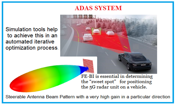
Problems in any part in the mm-wave 5G Smart Mobility Antenna system can ruin the functionality of the whole system, potentially costing hundreds of thousands of dollars and months of delays. Several sensors are needed to cover all short-range to long-range tasks, adding costs in a low-margin industry. Ansys HFSS solvers and high-performance computing can be used for the analysis of components like planar inductors, baluns, power dividers, and transmission lines. Parametric sweeps and goal-driven optimization is done inside Ansys Optimetrics. The efficient hybrid technology FE-BI is used in particular for antenna Design. For larger scenarios, HFSS SBR+ is used to simulate in-the-field antenna performance. For efficient overall workflow, ALinks interacts with the ECAD System for fast design transfer. Parasitic modeling is very important and can be easily achieved by either adding RLC Components directly to the 3D electromagnetic (EM) model or adding lumped components to the exported EM model inside the circuit environment of Ansys Electronics Desktop. Once the complete circuit model delivers the desired result for parameters such as Q factor, inductance, and gain, we combine all components into a system simulation using the Ansys RF option.
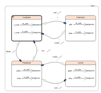
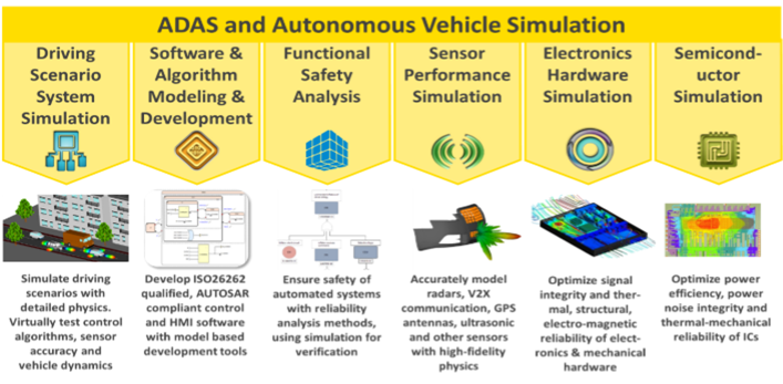
Just as in hardware development, simulation has a key role to play in software development. Developing and testing signal processing routines, sensor fusion algorithms, object recognition functions, control algorithms, and human-machine interface (HMI) software, with model-based software development techniques, makes the software robust, less error-prone, and safe. ADAS and autonomous driving technologies greatly multiply the complexity of vehicle systems. Not only do they create more possible causes of failure, but also many more failure cascade paths. Since ADAS and autonomous driving systems inherently have safety implications, any failure can easily be catastrophic, even fatal. Conducting functional safety analyses of such complex systems is tedious, error-prone, and vulnerable to gaps and flaws. Automated functional safety analysis tools are therefore essential to ensure the safety of ADAS and autonomous driving systems. Model-based embedded software development along with a qualified code generator greatly expedites embedded software development. Once the software models are validated, the generated code is guaranteed to be error-free thus eliminating unit testing of the code, and reducing overall software development efforts nearly in half.